A Series - Direct Heater Controls
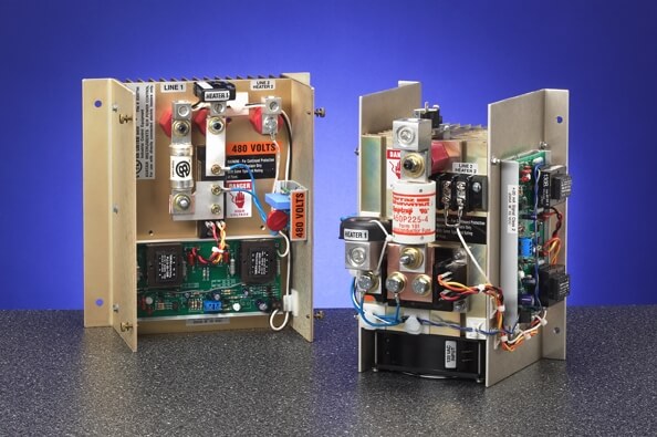
Avatar A1P and A3P S.C.R. Power Controls
- Phase Angle Proportional Control. No Temperature or Power cycling.
- Fast Response – 1/2 or power line cycle.
- Increased Heater Life; up to 7x longer.
- A1P features unique mono-couple design assures phase tracking for life.
- A3P has no phase restrictions.
- A3P features independent zero and span adjustments for each phase.Options: Soft Start for high inrush heaters (such as Tungsten). Exclusive multi-slope and controlled direct action system. Voltage Limit to prevent premature heater burn out and set point overshoot. Current Limit for high temperature elements.
![]()
Avatar A1Z, A3Z, A6Z S.C.R. Power Controls
- Zero Voltage Switching.
- Independent Automatic Synchronization. No phase rotation restrictions.
- Fast, Wide Ratio, Auto-variable time based proportioning.
- No third line hook up need on A3Z.
- Superior firing resolution.Options: “R” relay option: On/Off Control Model A6Z: 3 leg control, 6 SCR Switching
![]()
Avatar B Series – Transformer Primary Controls
Avatar B1P, B2P, and B3P Transformer Drivers
B1P Single Phase low power transformer control B2P Single Phase SCR higher power transformer control B3P Three Phase SCR transformer control
- Effective true proportional control for low voltage high amperage transformer coupled loads.
- B1P Series cost effective 120V to 277V 30 Amp units.
- Optional Current Limit & Soft Start available.
- Compact design/isolated heat sink.
Avatar C & D Series – Low Power Controllers
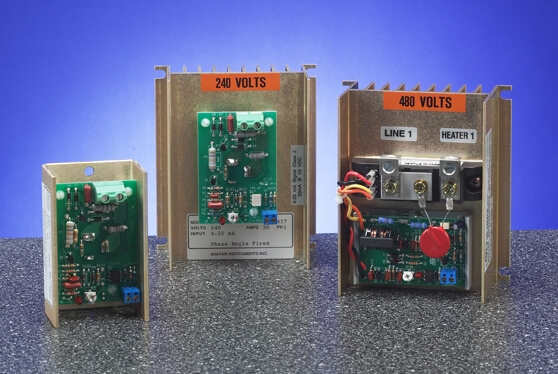
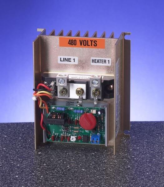
Avatar C1P Series Controls
With features unmatched in this price category:
- Linear Phase Angle Proportional Control. No temperature or power cycling.
- Fast Response – 1/2 of power line cycle. Ideal for open wire radiant or fluid heaters.
- Industrial Package TRIAC’s, easily serviceable. No flimsy board mounted toys.
- DV/DT suppression standard. Reduced probability of misfiring.
- Line Voltage Compensation in control range. Up to 300% better than “light dimmers.”
- Cost effective 20–60 Amp, 120V to 480V units.

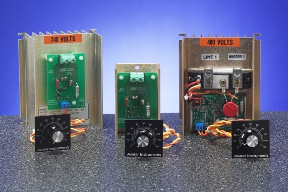
Avatar D1P TRIAC and D2P SCR Manual Potentiometer Controllers
The D1P is a proportional, infinitely variable power controller capable of delivering 1-98% of the applied line voltage to the directly connected electric heaters. This is accomplished by phase angle firing a TRIAC. The D1P will not control heaters with high inrush currents (tungsten lamps), transformers or motors.
The D2P is a proportional, infinitely variable power controller capable of delivering 1-97% of the applied line voltage to the directly connected electric heaters. This is accomplished by phase angle firing a pair of inversely connected SCR’s. The D2P will control heaters with high inrush currents (tungsten lamps), but not transformers or motors.
Avatar CP Series
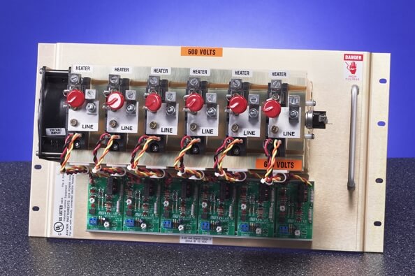
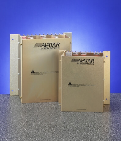
CP Series Multi-Zone SCR Power Controllers
The CP series SCR power controllers are multi-zone power controllers that can be configured for phase angle fired, zero voltage switched or on-off solid state contactor control of directly connected electric heaters. The CP will not control transformers or motors. This is accomplished by phase angle firing, or variable time based zero voltage switching a pair of inversely connected SCR’s. Up to eight zones available on a single chassis. Single phase and three phase options.
- Multi-Zone Phase Angle Fired or Zero Voltage Switched.
- 2 to 8 Zone Packages Available.
- Space Saving Design.
- 10–1200 Ampere output to 600VAC.
- No Transformers to wire up.
- Single & 3 Phase Packages.
- Optional Soft Start & Voltage Limit available on Phase Angle units.
Avatar R Series – Relay Replacement SCRs
Avatar R1 Series Controls
- Replaces Mechanical and Mercury Relays.
- Packages for 120V to 480V lines.
- Input Signal (Coil Voltage) 3-32 VDC, 24 VDC/VAC, 120 VAC.
- Up to 60 Amp Output at 55º C.
![]()